28-1-2016
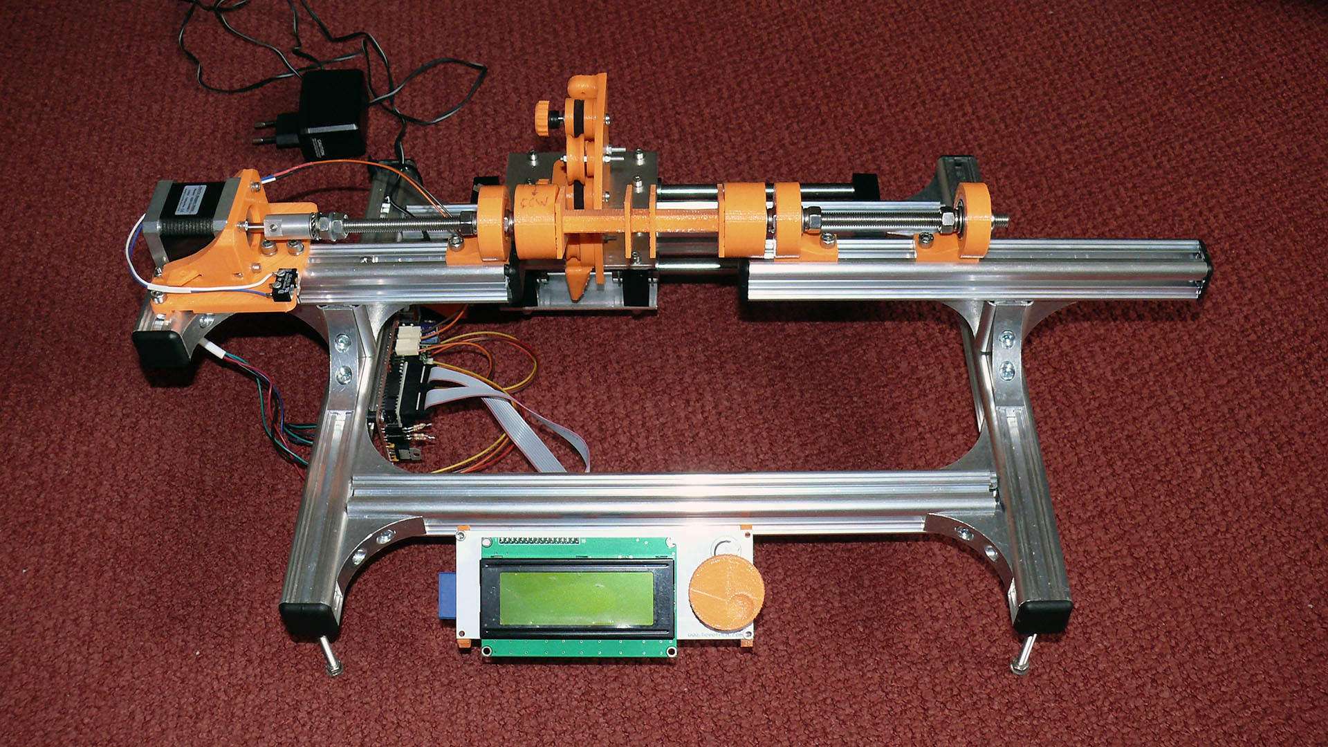
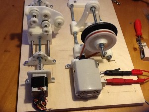
For those who want to understand how the wire is fed through, see this picture.
7-3-2014
Always nice to see someone actually use my files. In this case the wire tensioner 🙂
Thanks Oscar!!
24-2-2014
for those interested, I have put all the files on GITHUB
Nico
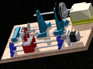
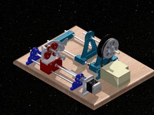
Having built my 3D printer and that I have a strong passion for Tube audio I decided to build my own coil winding machine. And as I have a lot of experience with Autocad Inventor 3D I wanted to design the whole thing first using Inventor before building any parts. And using Inventor also gives me the confirmation that it all fits.
Version 2.0
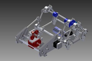
Having built experience from version 1 it was time to make a new design. But with a few changes.
- Use the RepRap concept and build it all using M8 threads, rods bults, washers and 3D printed parts.
- Less pulses per revolution
- Reuse any parts from version 1
- I still had a strong DC motor laying around I could use
- 12V power supply 6.
- 150W 40V booster for driving the DC motor (PWM)
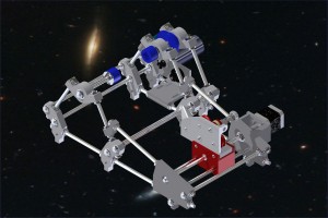
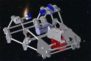
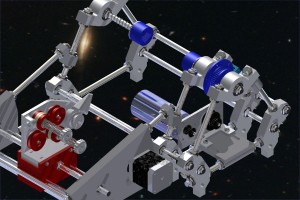
CAD design
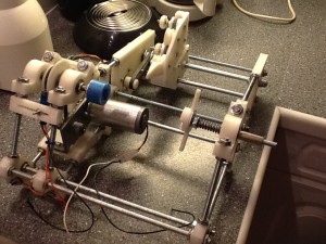
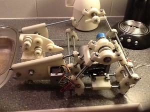
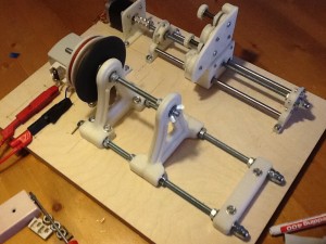
The real thing
Works great!! All threads run in 8mm bearings.
Version 1.0
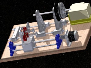
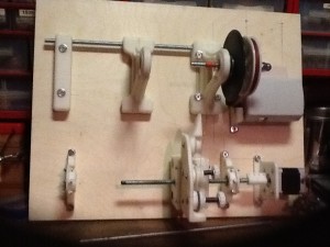
The concept was to use an old 60W sewing machine motor and gearing it down (about 1:10) for more driving power. A revolution disk generates pulses for timing.Tot control speed I used a Velleman kit. for the horizontal movement a stepper motor was used.
The pulses would generate interrupts on an Arduino Uno. Measuring the time between the pulses would make me able to calculate the steps and frequency needed for the stepper motor.
The CAD design
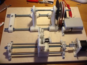
The real thing
Printed everything with my 3D printer (PLA plastic). All modelled parts are generatie from Autcad inventor using STL format. Parts are sliced with SLIC3R and printed with Repetier Host.
The results
Unfortunately it failed:
- The speed control chops 230V but as all windings within the motor as connected in series power drops dramatically. Unsuable.
- There were too many pulses going to the Arduino leading to errors.
- The supports for the horizontal movement were too weak.


Hi Nico
Did you ever manage to finish this?
Also do you have the sensor wheel as well?
Schalk
Hello m8
It’s an awesome project and design.
But without the électronics schematic and the arduino code,
it’s a useless piece of technology for us.
Is there any chance to have published the missing informations
to make this design usable for all.
Thank you very much for your work and reply.
Serge
If I had already designed the Software and schematic I would have made it available. Unfortunately that hasn’t happened yet. But what keeps you from building on the design? It isn’t that complicated after all. 6 pulses per revolution. I am using 8mm thread to move the head. Thread distance is 1.25mm.
My throughts were that if you know the wire thickness you know how much the head must move per rotation of the coil. To get a nice movement you can calculate between 2 pulses (6 per rotation) how many steps the stepper must make to avoid overlapping of coils.
Hi Nico, great job!. Could you explain how the wire tensioner works?. It is for two wire?. Could you explain which is the wire sequences in the tensioner?
Thanks!!!!
Regards
Alberto
Alberto,
I have added a picture on top.
It is for one (1) wire. So you have 2 tensioners for resistance. The pulleys small have builtin bearings to keep it running smoothly
This looks like a really cool concept! Is there any software (even if its incomplete) for it?
Actually I picked it up again recently. Got all the component on a board of persplex and I’ll see if I have some time toe finish it off. Never expected it to be wathced so many times.
Ah ok,
Well sorry those were dumped a long time ago. It was a crap solution so I felt no need to save them.
Hi Nic0,
it only have design files for version 2. but i need deign files for version 2. i’m very much thankful to you if you can consider my offer.thanks.
*deign files for version 1
Hi,
Thank you for your reply. Can you upload design files (inventor) of version 1? it is a great help
Check the link just below the top picture.
Hi,
it seems to be a great project. But still i can’t understand that how it works?
can it wind small air coils? please can you enplane the working mechanism of this DIY project? Thank you
Basically the machine is mechanically ready. The electronics still need to be developed. There is a pulse generator on the rotating axis generating 6 pulses per rotation. The time between each pulse determines the speed the horizontal movement needs to get. This can be calculated based on the width of the wire leading to the number of steps on the stepper motor. A bobbin can be put on the rotating shaft as the middle piece can be taken out.
But like I said on the page itself, I do not have the time to continue the project so I gave the drawings and files free.
Impressive engineering!
Another call for github sharing. Inventor files are fine, or STL. If you plan to share the files, let me know, I would build such a machine.
Thanks
Hi Jerome
I put the link on the site now. Same page. You might have to edit one or another.
But anyway have fun
Regards
Nico
Hi Nico,
Looks very nice. I’m also interested in the files. Maybe a zip through wetransfer?
Cheers!
Corneel
Hi Nico:
Thank you for reply!!
You have some data about the motors?
One video might be enlightening :)…
All the best..
Greetings from Argentina.
Alberto.
Hello Nico:
Very good proyect!, Felicitaciones!
I am starting with a winding machine proyect for experiment with power transformers for my own use, your proyect is a light in my way :). My idea is the same, dc motor with encoder, and only one stepper motor controlled with arduino.
Can you share the inventor files? I can print the pieces in the 3d printer of one friend.
Thank you!
All the best.
Alberto.
Hi Alberto
I can send the inventor files. But I doubt hotmail will accept the size of the zip file. I’ll see if I can put them on Github later this week.
Hello,
I was wondering if you would share the parts/list needed for building your designed coil-winding machine as a DIY kit?
Looks really great, I’m looking for a simple DIY design.
How does it preform? Got software for it too?
Kind Regards
Hi Coilwinder
Never thought about that. My intention was when I finally find the time to get the electronics in, to put it on Github as open source. I just built it… because I could 🙂
And I still have to write the software for it. But I am busy doing all kinds of Arduino projects that are paying off, So you understand where my priority is :).
Regards
Nico
Hi Nico,
It would be very cool if you post it on Github as open source!
Just the printed parts for a start 🙂 🙂
If you share it in the open source I can help with software too, just an idea 🙂
For the electronics, I’m thinking to use a Sanguinololu board.
Regards!
Wel actually I was thinking about a simpler (and cheaper solution :))I designed a simple shield for the Arduino with just a power mosfet for PWM on de winder motor and a pololu driver for the stepper. That is about all you need and some inputs for the sensors. I have the design ready. If it works I can always have them made at ITEADstudio. The PCB bare would cost something like
5.00 US$ (blue color[red is Sparkfun 🙂 / green is too common :)] excl. shipping. And they make excellent quality PCB’s.
Just have to find the time.
All the files are however in Autocad Inventor 3D. I generate the STL files. I don’t mind sending all the Autocad files if you like or the STL’s. I am probably too busy right now anyway.
Regards
Nico