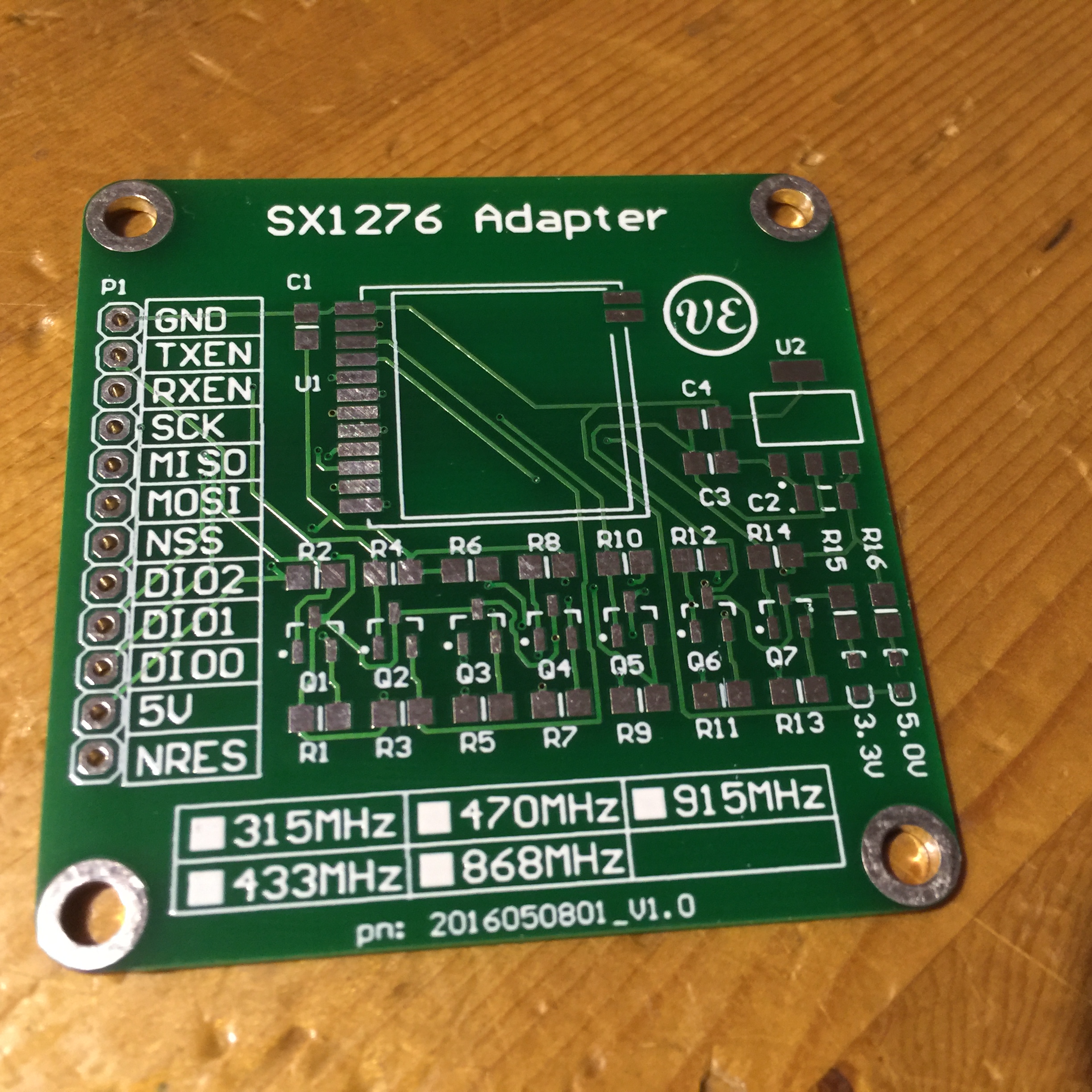
7-7-2016 it Works!!
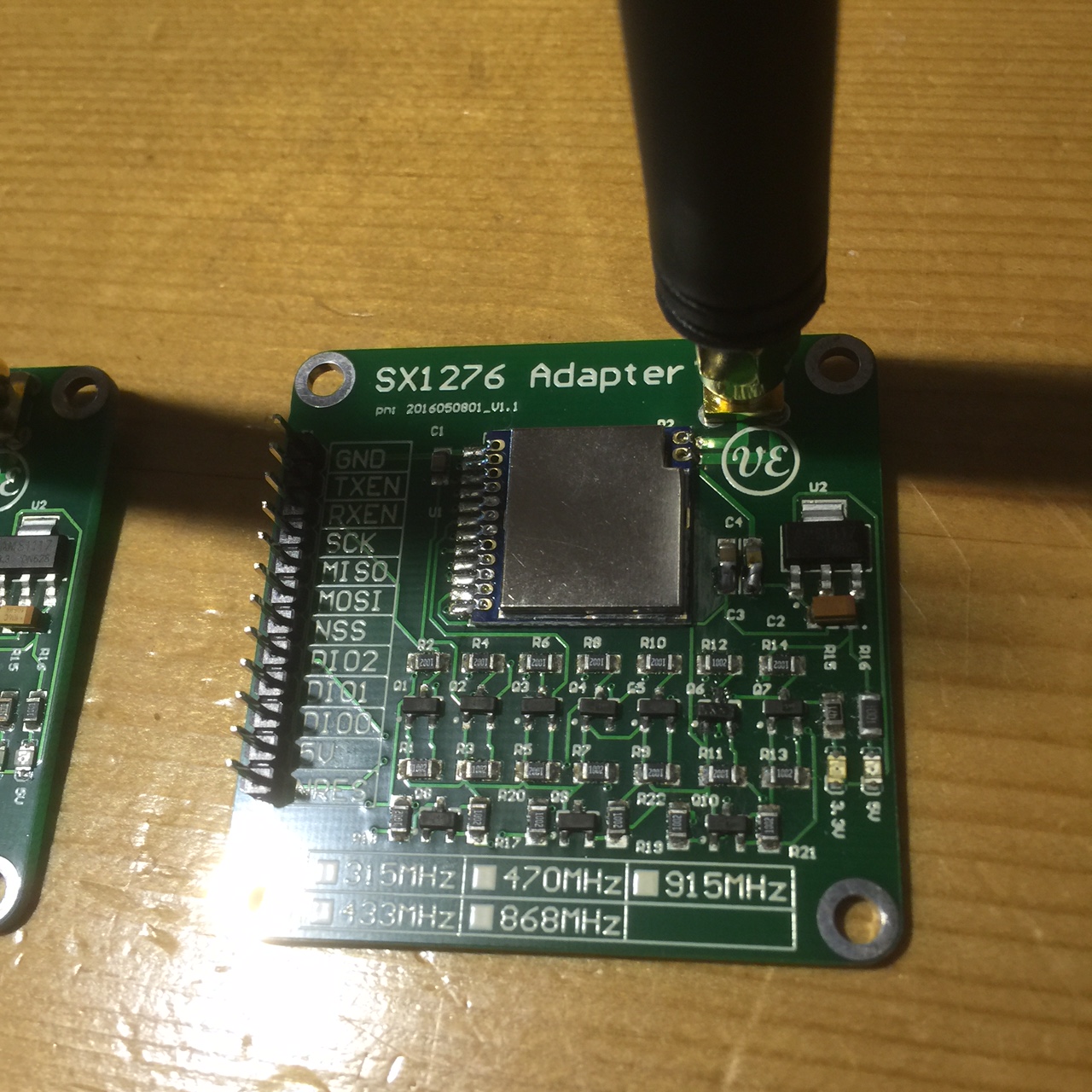
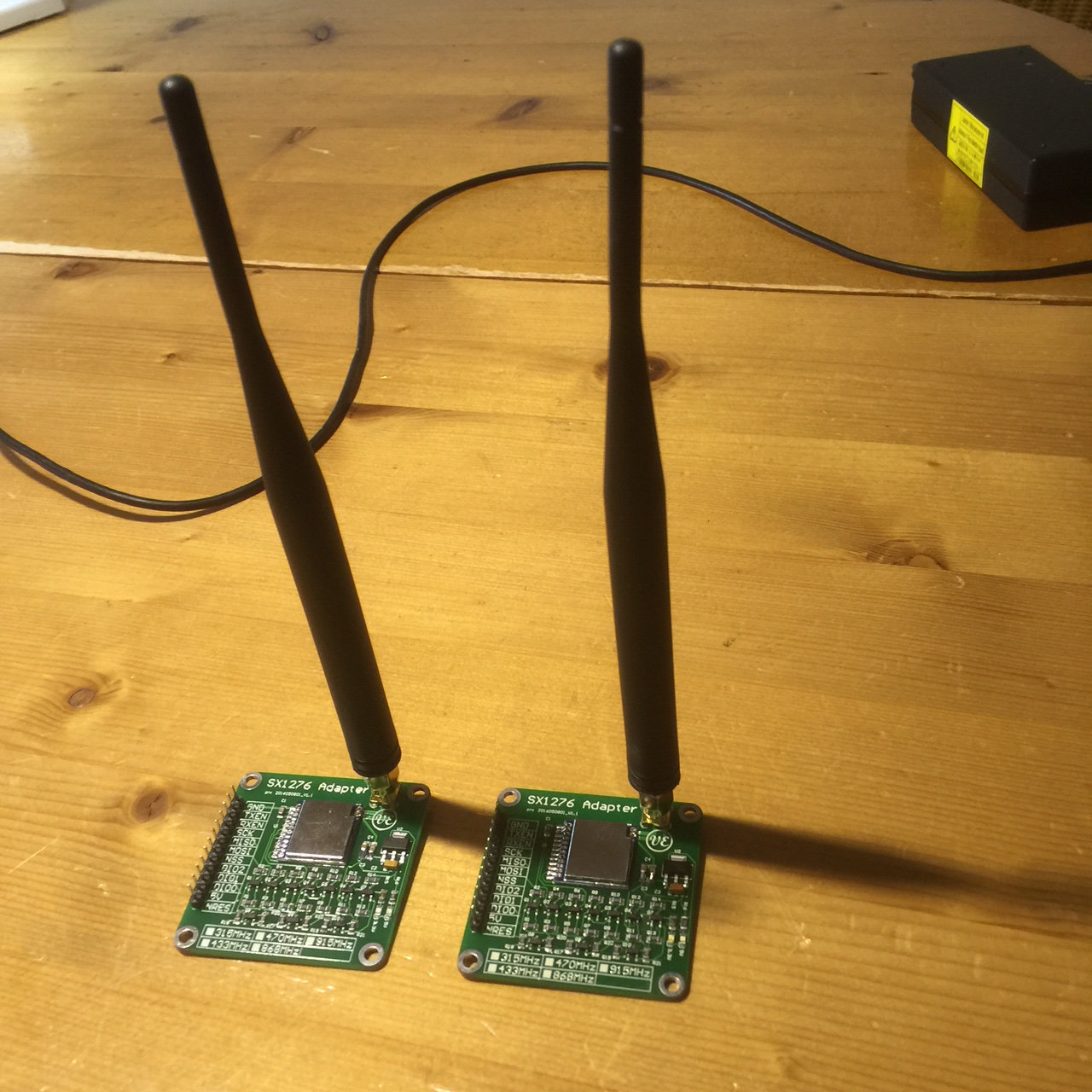
Redesigned my board and got them in last week. Soldered them without the modules first and did some electrical tests. All level shifters work now. So I soldered the module in and time to start testing. I had written a small piece of code to read all registers and to my satisfaction the communication works. So time to add some real code. Matthijs Kooijman has ported the LMIC 1.5 libraries so they could be used on Arduino see link. I flashed 2 arduino’s with the ‘raw’ ino. No compile problems and It works…. I modified the raw.ino to flash a led on the other arduino so I could see in the field if one node could flash a led on the other and vice versa. Put one on the nodes in my house at the top floor. The other in my car and started driving.
Sofar I reached about 1Km distance. A bit low stil but not a bad result though. Time to learn a bit more in this project.
4-6-2016 afternoon Too good to be true…..
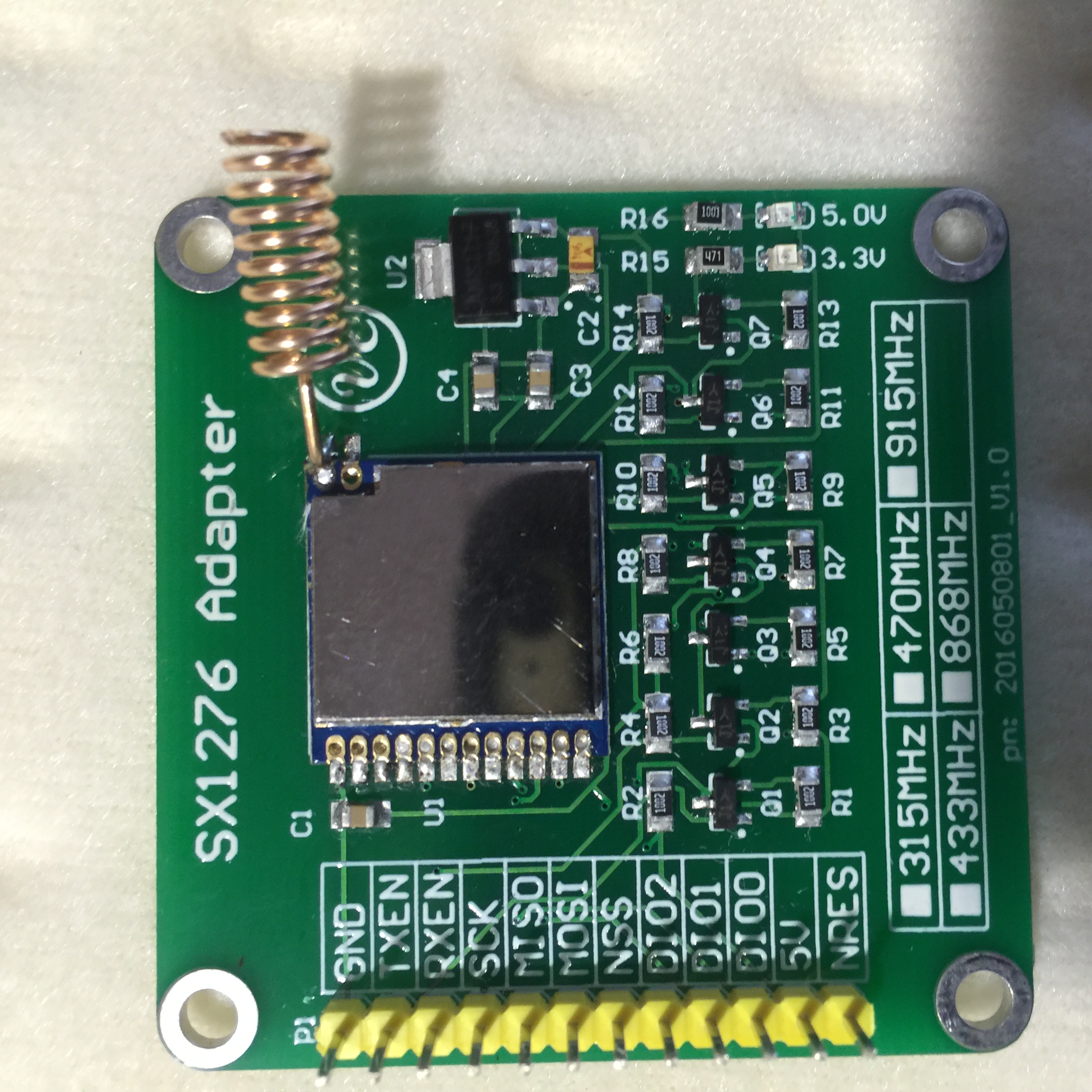
As I had 2 SX1276 modules, soldered both of them. Should have some confidence after all… The good news is that everything soldered well.
The bad news however:
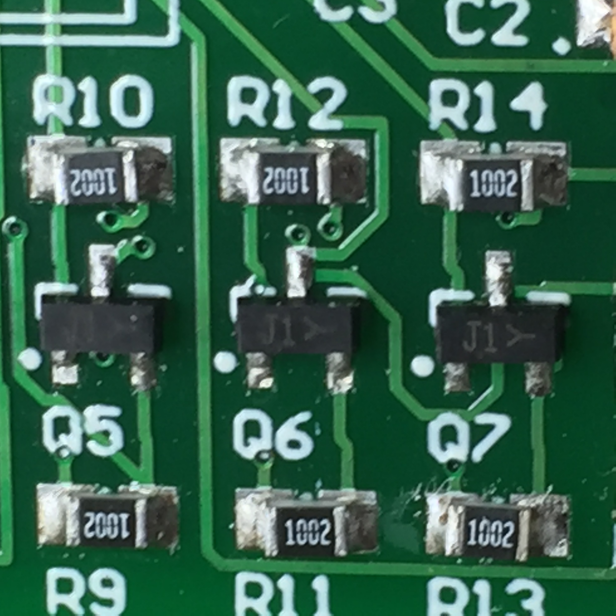
- I got the wrong part for BSS138. I received after some investigation that part code J1Y = KSA1298. Which is a transistor and not a small fet.
- The Tantalum Elco I used short circuited with 5V input while the requested part was specified for 10V
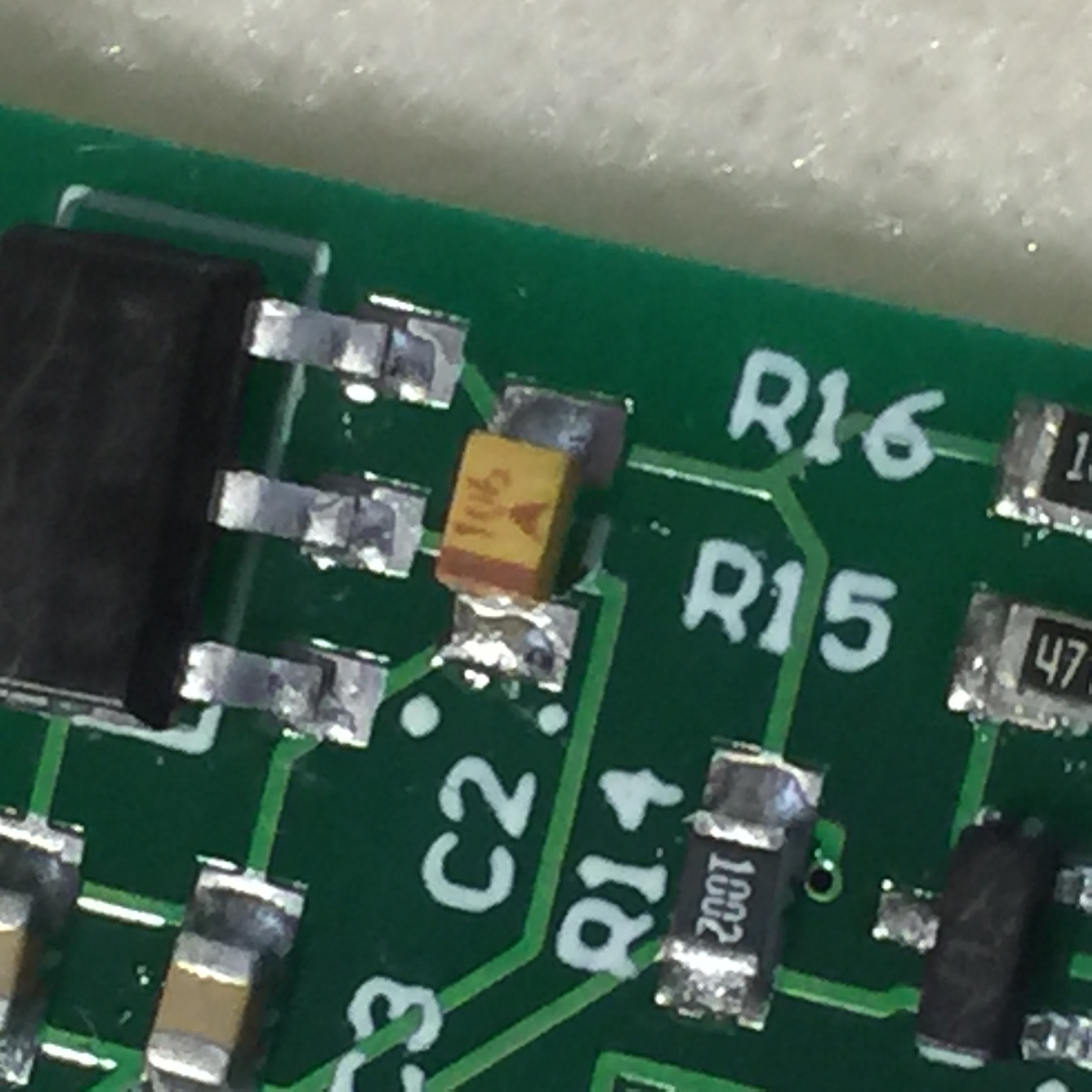
- I did not have an AMS1117 component in my Library. Unfortunately I should have checked the datasheet. The TAB of the component I used was connected to GND. With the AMS1117 it is connect to the output.
Both parts came from AliExpress so this is a bit disappointing and frustrating. So I back to square one.
The good news is that I do not need to make a new stencil. the board wil get some corrections/enhancements but the stencil stays the same.
4-6-2016
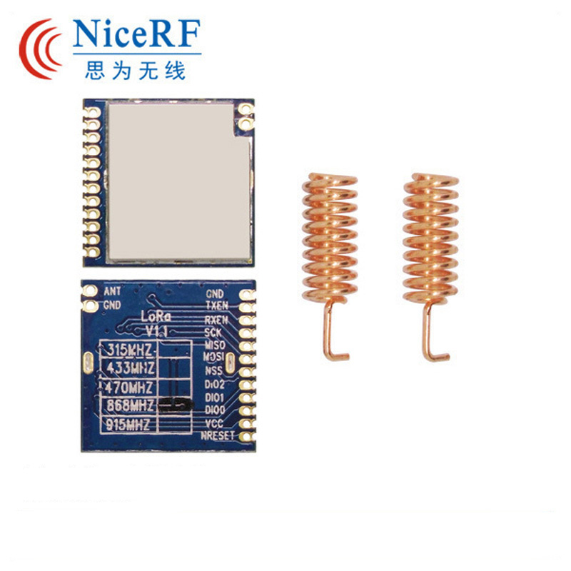
I bought a couple of low cost LoRa transceivers at AliExpress to try out.
I think there is a huge potential in this form of communication due to its transceiver range. The only to find out is to start experimenting. The modules I bought have 1.27mm spacing pins. I have seen a site where someone soldered thin wires to 2.54mm header pins but I think that is too fragile for me. Reason to design a little adapter board for it.
Most of these modules operate at 3.3V and not all are 5v tolerant. I decided to develop a small adapter board with level shifting and its own onboard linear regulator to use it on the arduino platform.
It is a first try out. It could be that I need some modifications in future before the final design is made.
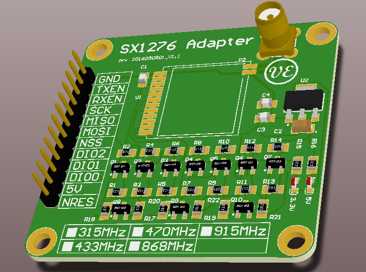
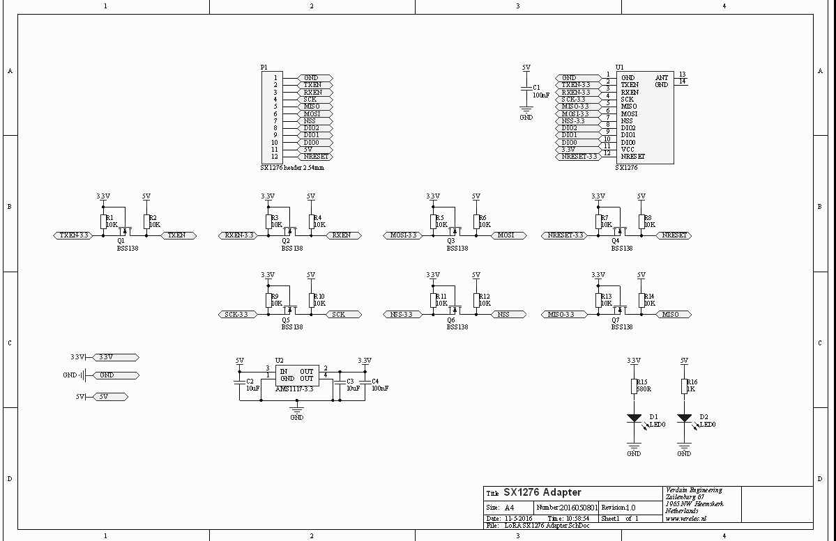
This is the first design where I use level shifters with the BSS138 mostfet and a couple of 10K resistor. All is SMD (0805). My first design was with 4050 level shifers, but using the mosfet and a couple of resistors cuts the price (I know it is all a matter of cents).
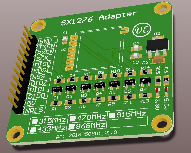
Any this is the schematic and 3D board design.
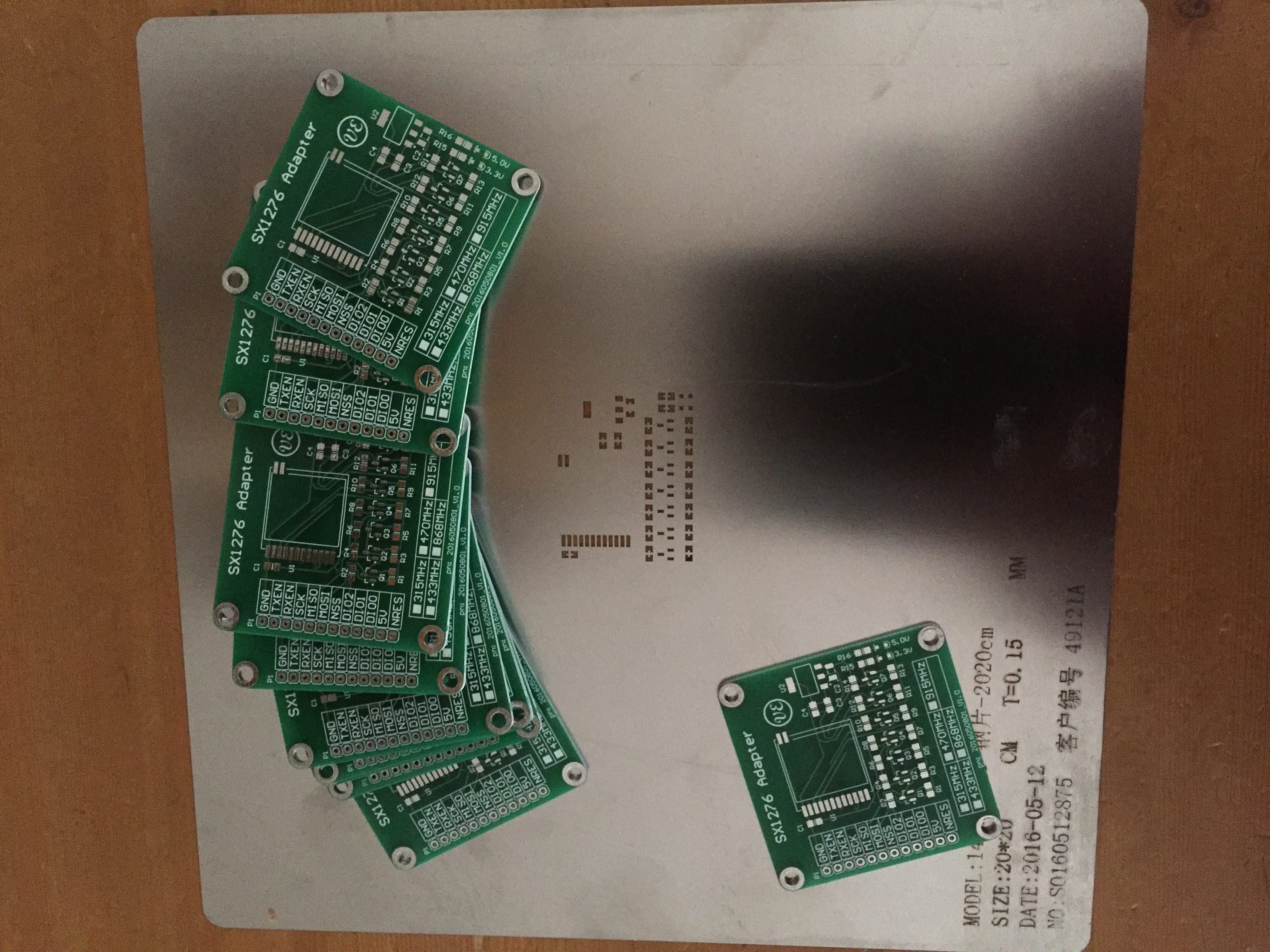
The boards are made in China (IteadStudio.com). So far I have had good experiences with them. The Stencil was ordered at Itead as well. Made of stainless steel it costs a bit more but looks great.
The next step is populate the boards. Hopefully I can do this this weekend.

